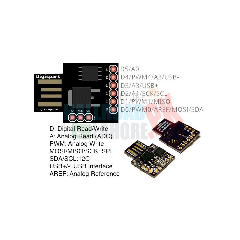
The ATTINY85 development board is designed to develop devices with minimal peripheral requirements and the ability to directly connect to the USB interface of a computer for programming and debugging. No cable is required to connect to a computer - the controller plugs directly into the USB connector. The controller has 6 outputs and all of them are available for use. Two are reserved for working with the USB interface, one is connected to an LED. For development, you can use the Arduino IDE (OSX / Win / Linux).
The device can be powered from a USB interface, an external source with a voltage of 5V and a voltage of 7V to 12V from an internal voltage stabilizer 5V 500mA. The power supply is switched automatically.
Controller pin functions:
- P0 - ARef, SDA, DI, PWM
- P1 - DO, PWM
- P2 - D / A, SCK
- P3 - D / A, USB +
- P4 - PWM, D / A, USB-
- P5 - D / A
Characteristics:
- Microcontroller: ATTINY85
- Internal oscillator: 8MHz
- Built-in frequency multiplier: 8
- Program memory size: 8KB (6KB available)
- Hardware interfaces: SPI, I2C
- PWM: 3 channels
- ADC: 4 channels
- Indicators: Power Status (Pin0)
Specifications:
- Support for the IDE 1.0+ (OSX/Win/Linux)
- On-board 500ma 5V Regulator
- Built-in USB (and serial debugging)
- Power via USB or External Source - 5v or 7-35v (automatic selection)
- I2C and SPI (vis USI)
- PWM on 3 pins (more possible with Software PWM)
- 6 I/O Pins (2 are used for USB only if your program actively communicates over USB, otherwise you can use all 6 even if you are programming via USB)
- 8k Flash Memory (about 6k after bootloader)
- ADC on 4 pins
- Power LED and Test/Status LED (on Pin0)


